Load Balancers
This lesson explores AWS Elastic Load Balancers and their configuration for high availability, auto-scaling, and fault tolerance in cloud environments.
In this lesson, you'll explore AWS Elastic Load Balancers (ELB) and learn how to configure them for high availability, auto-scaling, and fault tolerance in your cloud environments.
Why Load Balancers?
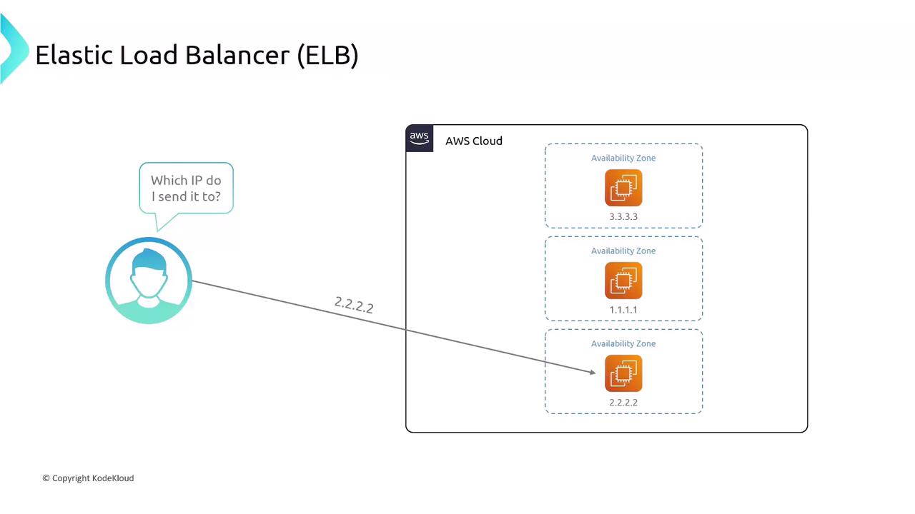
Imagine hosting your web application on a single EC2 instance at public IP 1.1.1.1. If that instance fails, your site goes offline. To add redundancy, you deploy instances across multiple Availability Zones:
- EC2 A: 1.1.1.1
- EC2 B: 2.2.2.2
- EC2 C: 3.3.3.3
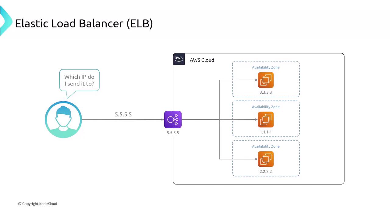
Which IP address should your users access? Manually switching between IPs is cumbersome and exposes internal details. A load balancer provides a single, stable endpoint that intelligently distributes requests to healthy backends.
Once deployed, the ELB abstracts individual instance IPs and automatically routes traffic:
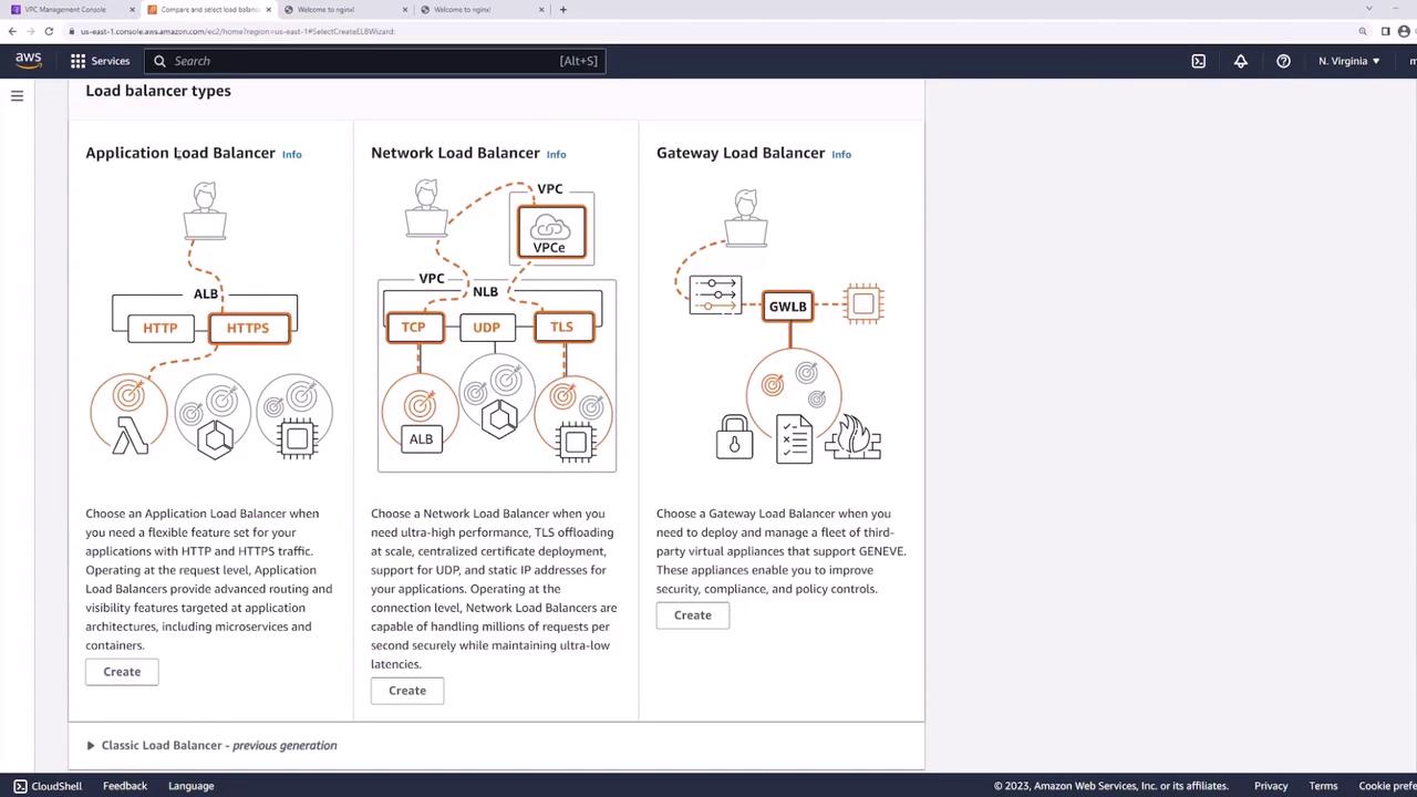
Types of AWS Load Balancers
AWS provides three managed load-balancing options to suit different workloads:
| Load Balancer Type | OSI Layer | Protocols | SSL Termination | Use Case |
|---|---|---|---|---|
| Classic Load Balancer (CLB) | 4 & 7 | HTTP, HTTPS, TCP, SSL | Yes (one certificate) | Legacy workloads |
| Application Load Balancer (ALB) | 7 | HTTP, HTTPS, WebSockets | Yes (multiple) | URL/path-based routing |
| Network Load Balancer (NLB) | 4 | TCP, UDP | No | Ultra-low latency transport load |
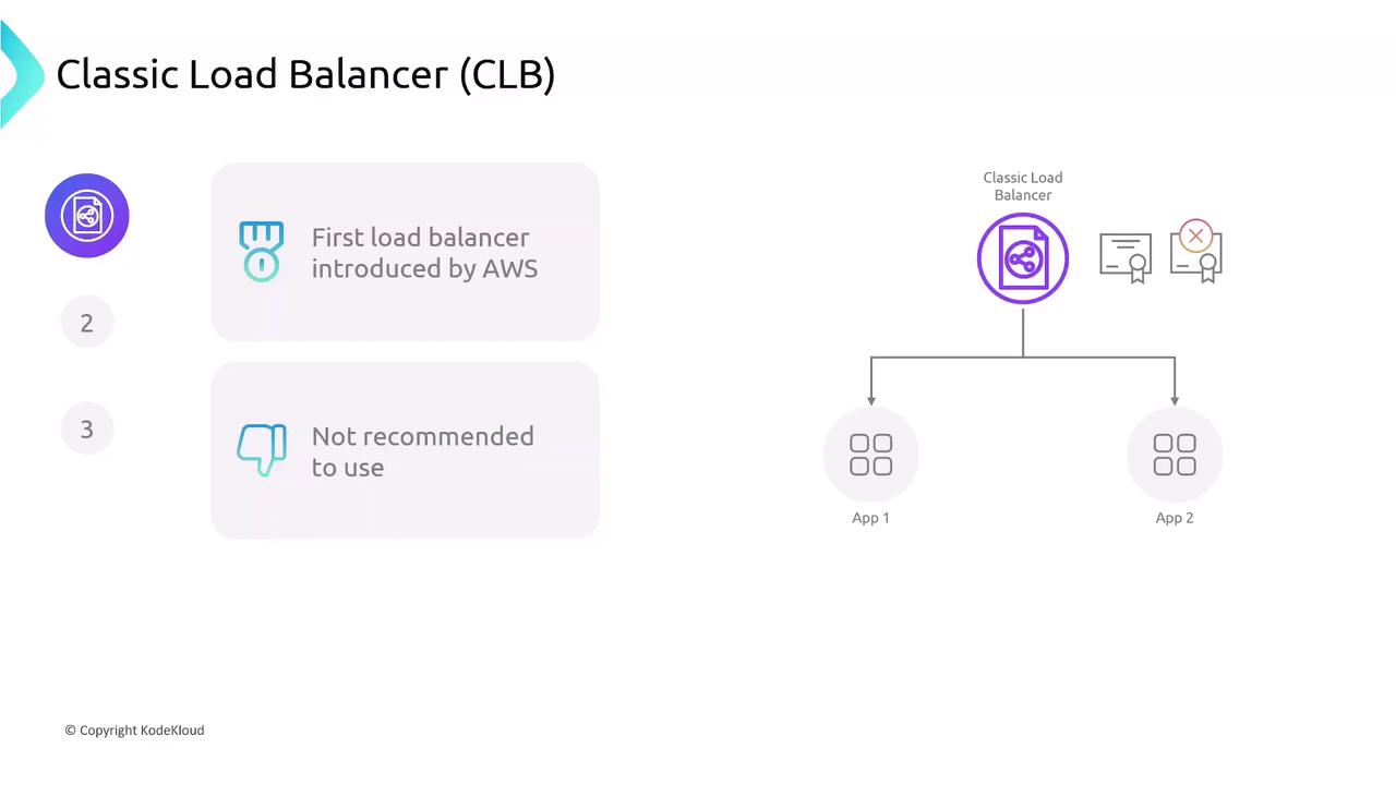
1. Classic Load Balancer (CLB)
The original AWS load balancer supports HTTP, HTTPS, TCP, and SSL but lacks modern features like multiple certificates and advanced routing.
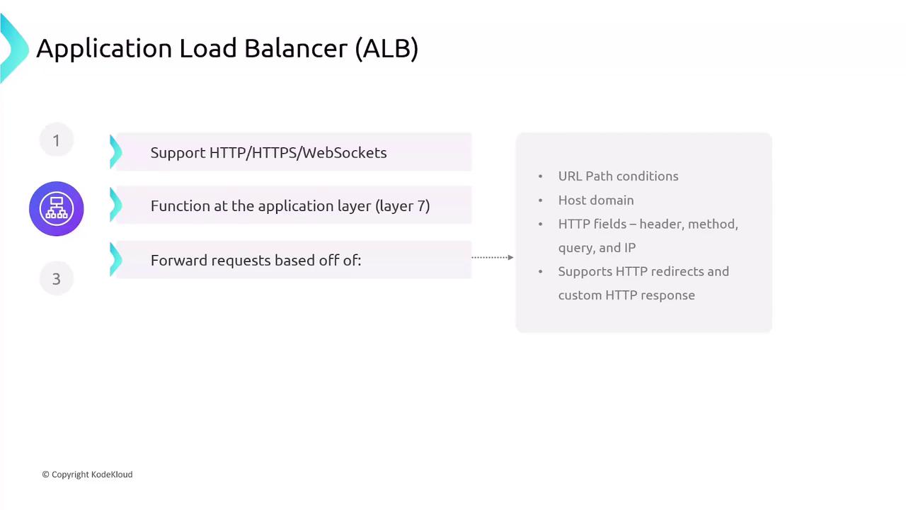
2. Application Load Balancer (ALB)
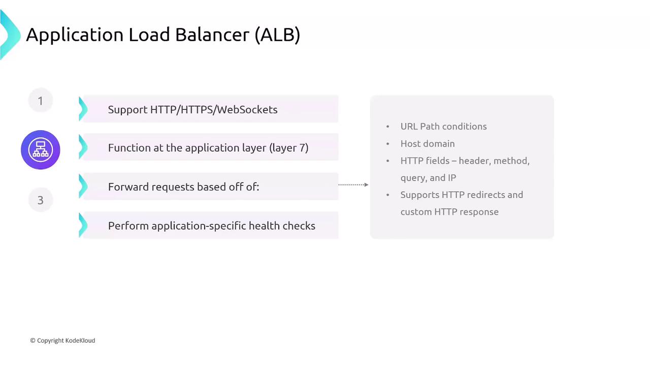
ALBs operate at the application layer (Layer 7) and excel at HTTP, HTTPS, and WebSocket traffic. They provide content-based routing and host/path-based rules:
- URL path and host header conditions
- HTTP methods, headers, query strings, source IP
- HTTP redirects and custom responses
- Application-level health checks
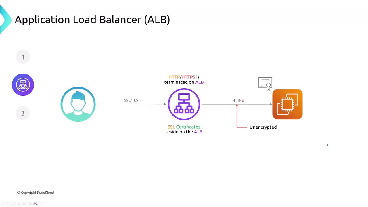
ALB Traffic Flow and SSL Termination
Application Load Balancers terminate SSL/TLS connections, decrypting traffic at the edge. Your SSL certificates reside on the ALB, and you can choose to forward decrypted traffic to backends over HTTP or re-encrypt using HTTPS.
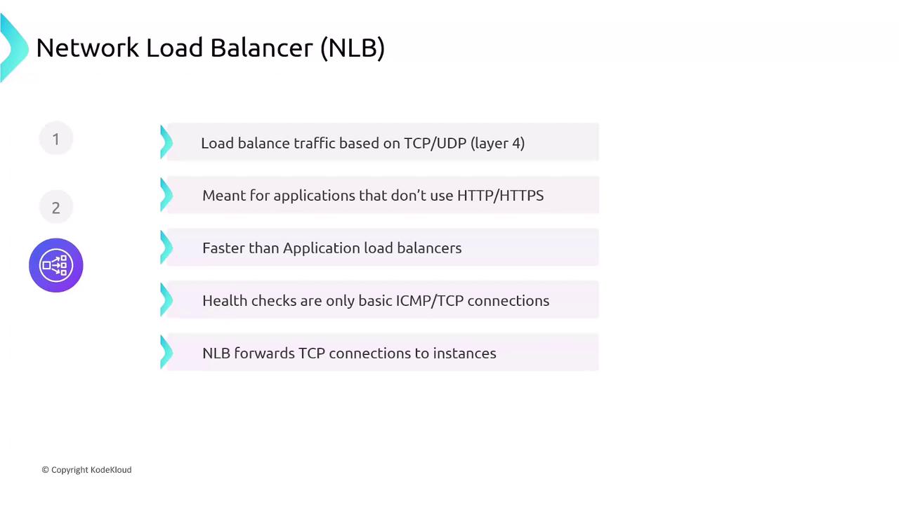
3. Network Load Balancer (NLB)
Operating at the transport layer (Layer 4), NLBs handle millions of requests per second with ultra-low latency. They forward TCP/UDP connections directly to targets without TLS termination.
- High throughput and low latency
- Static IP support and Elastic IP attachment
- Basic transport-level health checks (TCP)
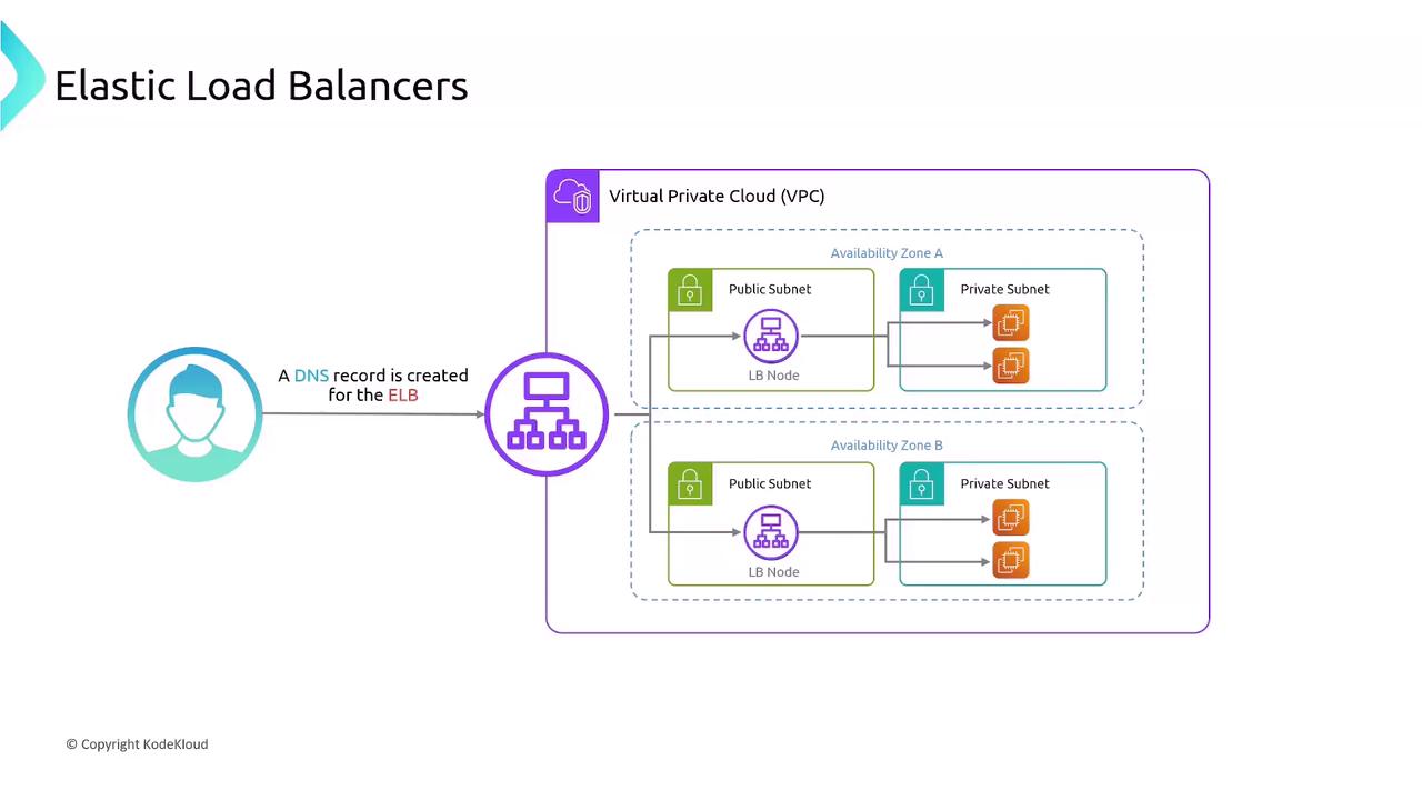
ELB Architecture in a VPC
When you create an ELB, AWS launches a load-balancer node in each selected subnet (one per AZ). Clients resolve the ELB’s DNS name, and AWS distributes traffic across all nodes, which in turn forward requests to registered targets.
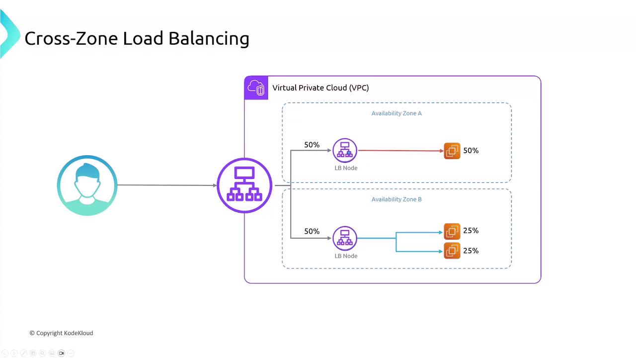
Cross-Zone Load Balancing
By default, each ELB node only routes traffic to targets in its own Availability Zone, which can cause uneven distribution if instance counts differ. Enabling cross-zone load balancing ensures each node spreads requests across all zones evenly.
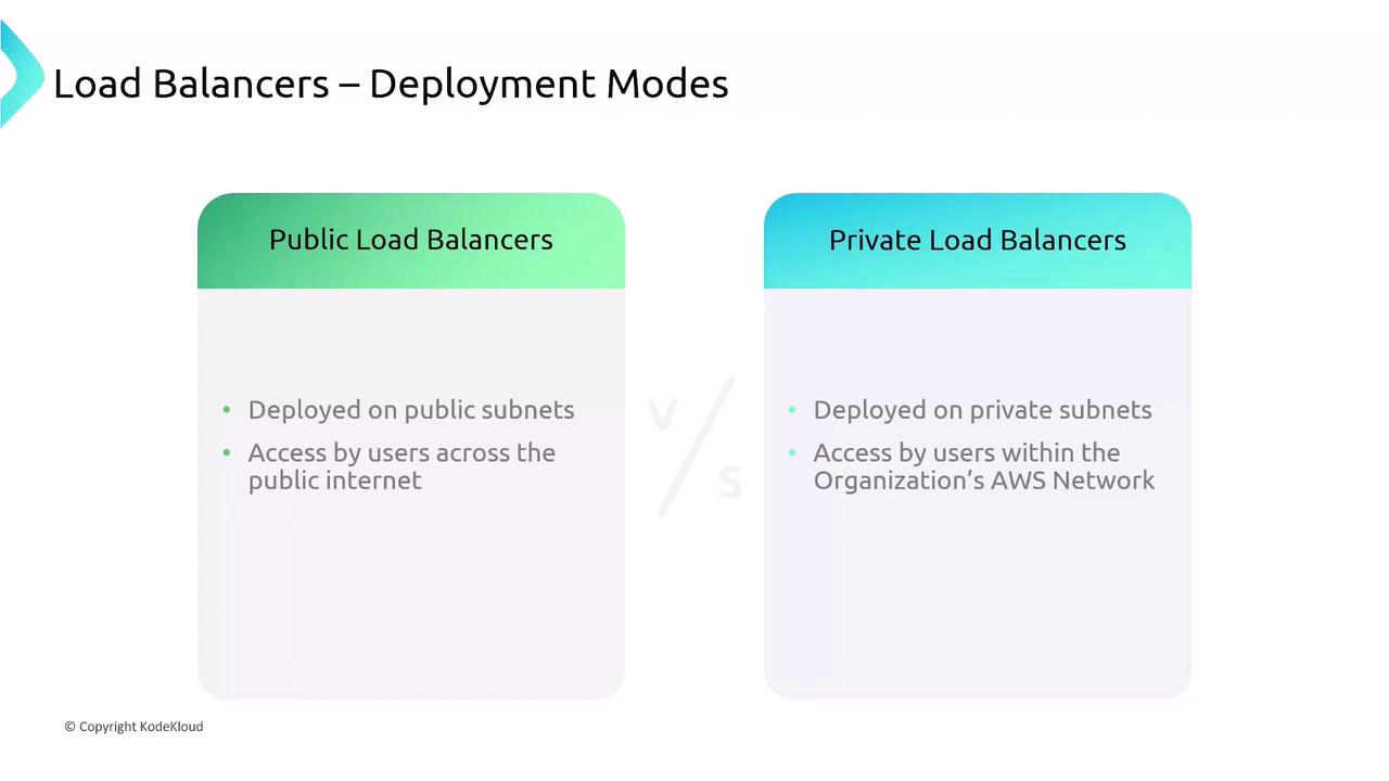
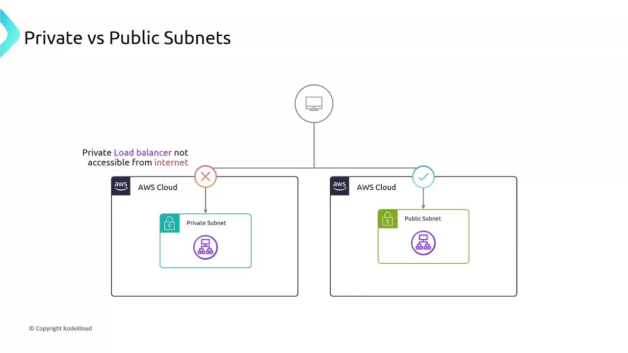
Public vs. Private Load Balancers
When deploying an ELB, you specify subnets:
- Public Load Balancer: Internet-facing on public subnets
- Private Load Balancer: Internal-only on private subnets
Example: Multi-Tier Application
Consider a two-tier application in a VPC across two Availability Zones:
- API Layer
- EC2 instances hosting your public API
-
Internet-facing public ALB distributes incoming user traffic
-
Database Layer
- EC2 instances running database or business logic
- Internal private ALB restricts access to only the API servers
This setup exposes your frontend securely while keeping your backend protected.

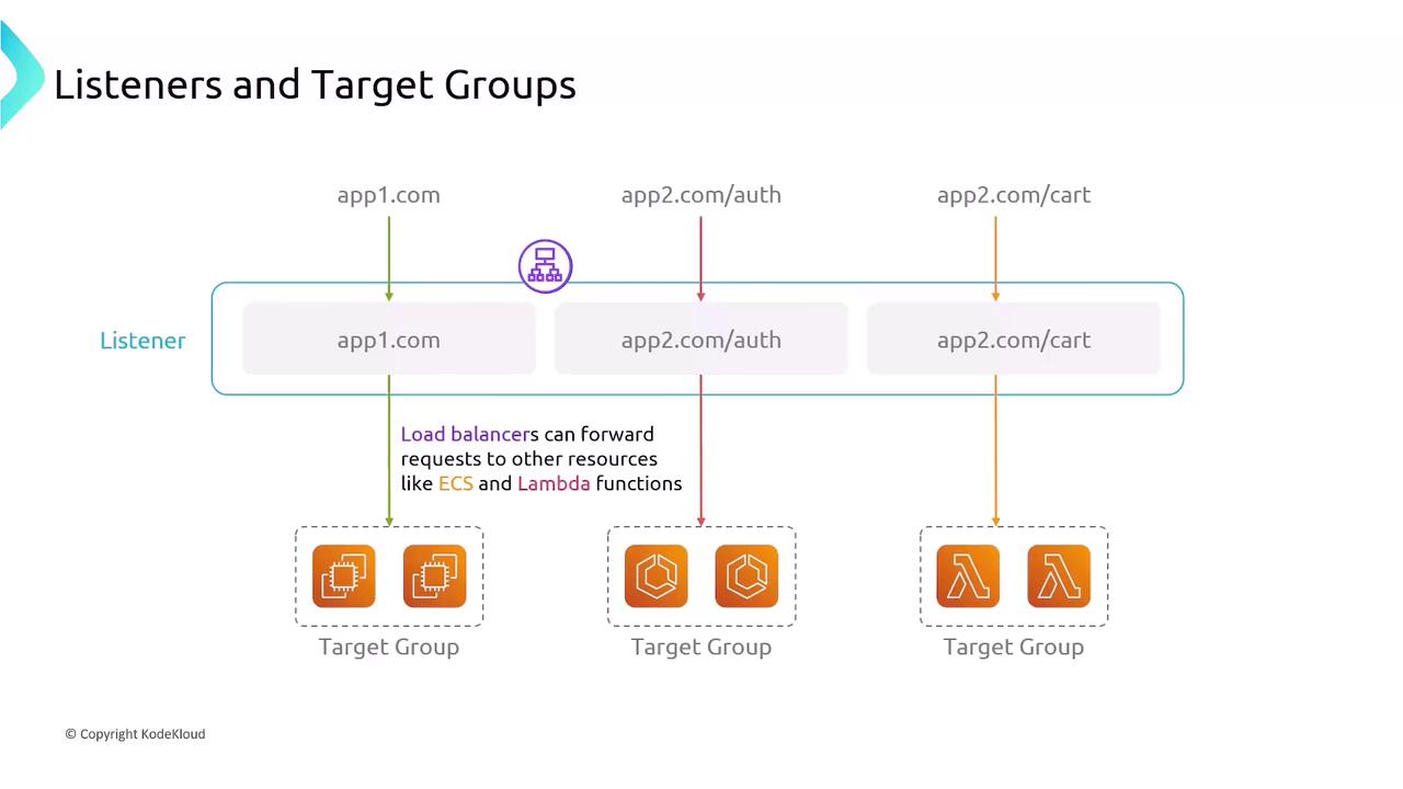
Listeners and Target Groups
Listeners and target groups define how ELBs receive and route traffic:
- Listeners: Check for incoming connections on a specific protocol and port. ALB listeners support content-based rules (host, path, headers).
- Target Groups: Logical groups of endpoints (EC2 instances, IPs, ECS tasks, Lambda functions). Each listener rule forwards traffic to one or more target groups, with configurable health checks.
Summary
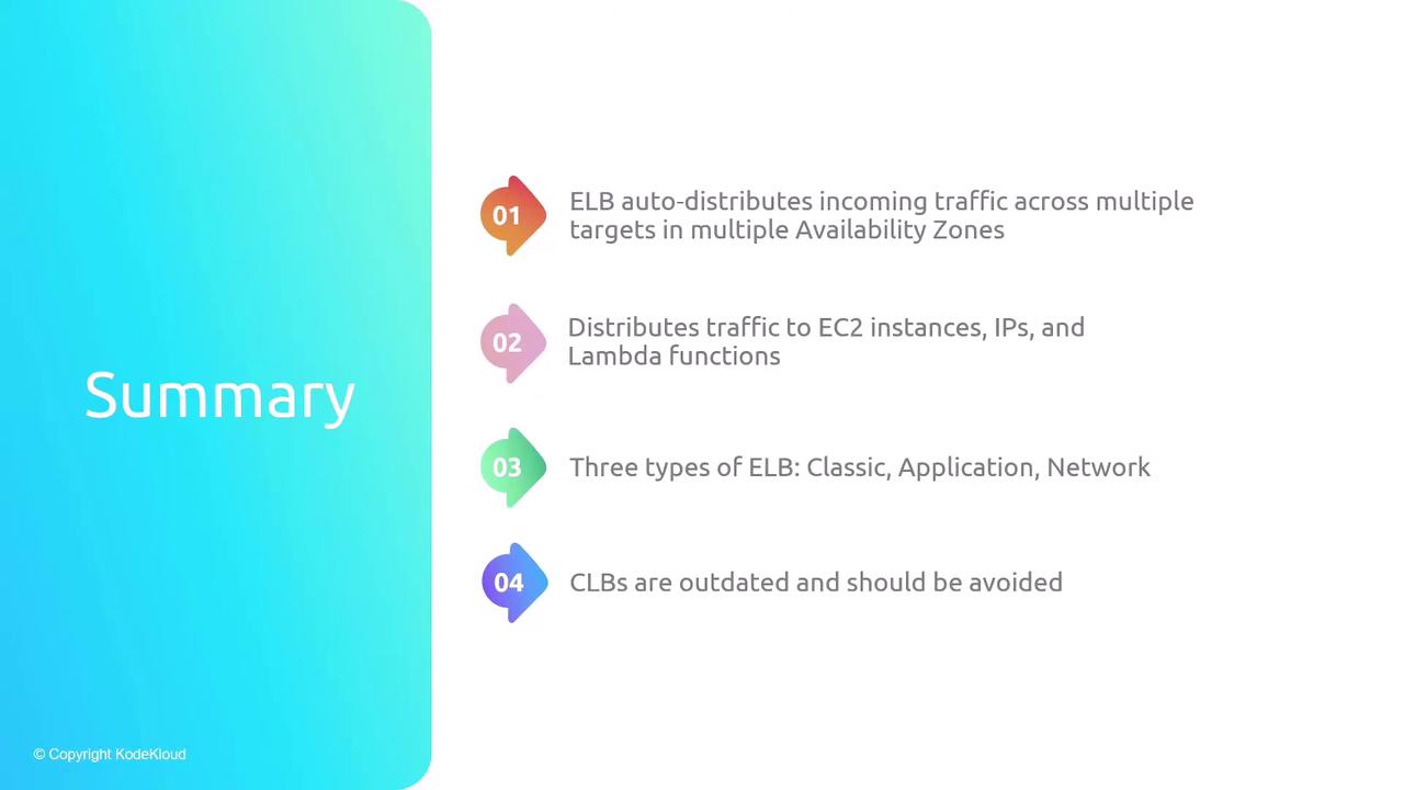
- ELBs distribute traffic across multiple targets and AZs automatically.
- Supports EC2 instances, IP addresses, containers (ECS), and Lambda functions.
- Classic (CLB): Legacy; limited features, one SSL cert.
- Application (ALB): Layer 7 routing with advanced rules and TLS termination.
- Network (NLB): Layer 4 transport load balancing with ultra-low latency.
- Cross-zone load balancing for even traffic distribution across AZs.
- Listeners parse connections; target groups manage backend health and routing.
References
- AWS Elastic Load Balancing Documentation
- AWS Networking Fundamentals
- Designing Highly Available Systems on AWS (Whitepaper)
- ELB auto-distributes incoming traffic accros multiple targets in multiple Availabitiliy Zones
- Distributes traffic to EC2 instances, IPs, and Lambda functions
- Three types of ELB: Classic, Application, Network
- CLBs are outdated and should be avoided
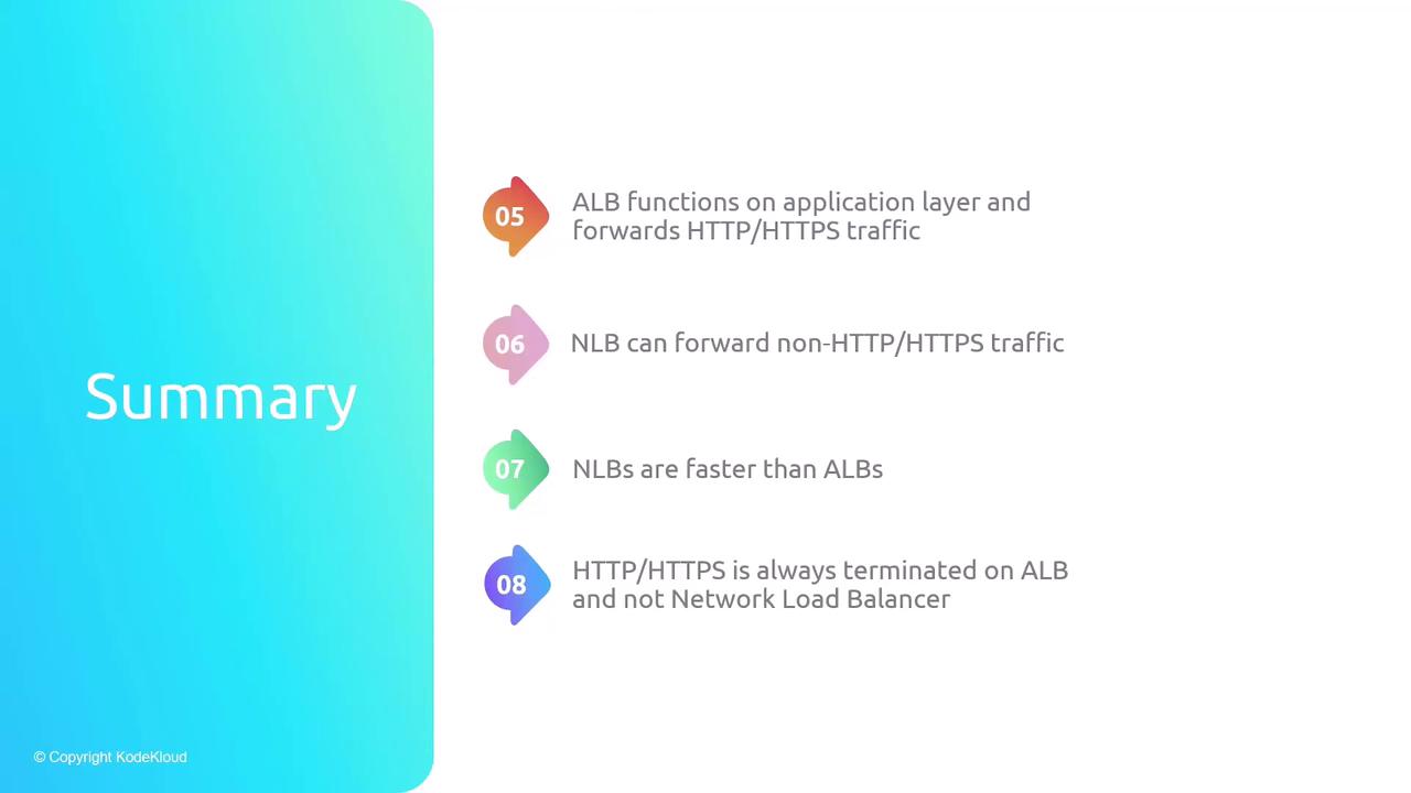
- ALB functions on application layer and forwards HTTP/HTTPS traffic
- NLB can forward non-HTTP/HTTPS traffic
- NLBs are faster than ALBs
- HTTP/HTTPS is always terminated on ALB and not NLB
- Cross-Zone Load Balancing equally distributes traffic across aall instances in all AZs
- A listener matches traffic based on rules and handles connection requests
- Target groups route requests to registered EC2 instances based on specified protocol and port
This hands-on tutorial guides setting up an AWS Application Load Balancer to distribute HTTP requests across two EC2 web servers running Nginx.
In this hands-on tutorial, you’ll set up an AWS Application Load Balancer (ALB) to distribute HTTP requests across two EC2 web servers running Nginx, each in a different Availability Zone. By the end, you’ll have a resilient, internet-facing load balancer serving content from both servers.
Prerequisites
- Two t2.micro EC2 instances (web-server-1, web-server-2) with Nginx and distinct landing pages.
- A VPC configured with an Internet Gateway.
- Two public subnets in us-east-1a and us-east-1b.
| Resource | Description | Details |
|---|---|---|
| EC2 Instances | Web servers | web-server-1 (us-east-1a), web-server-2 (us-east-1b) |
| VPC | Virtual Private Cloud | Includes an Internet Gateway and public subnets |
| Public Subnets | Hosts web servers | 10.0.201.0/24 (AZ a), 10.0.202.0/24 (AZ b) |
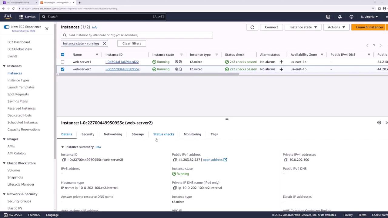
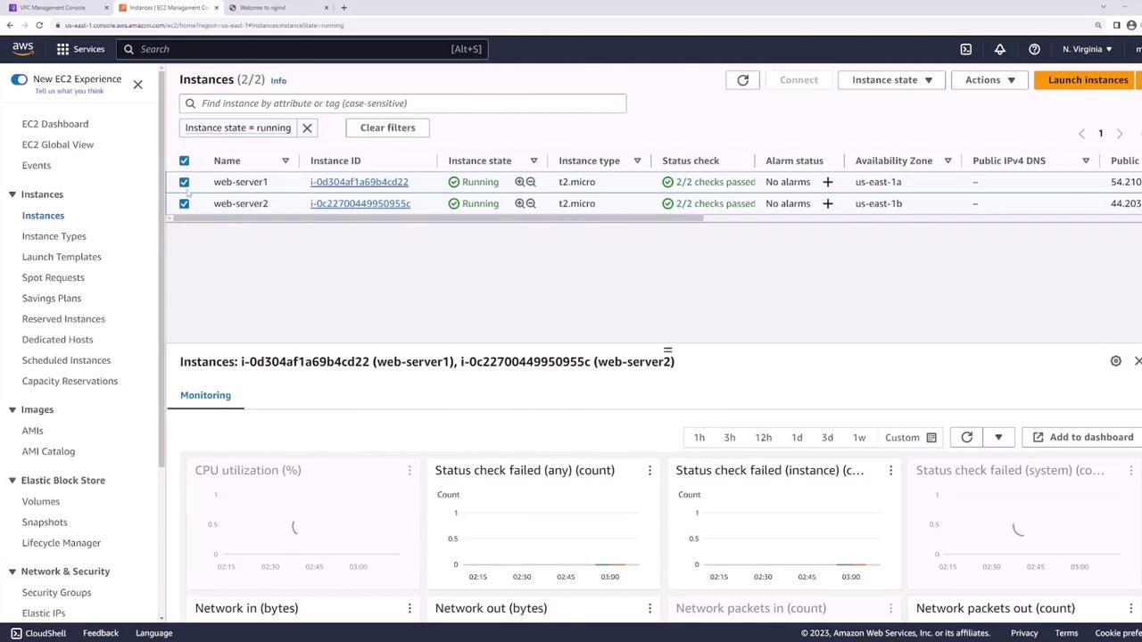
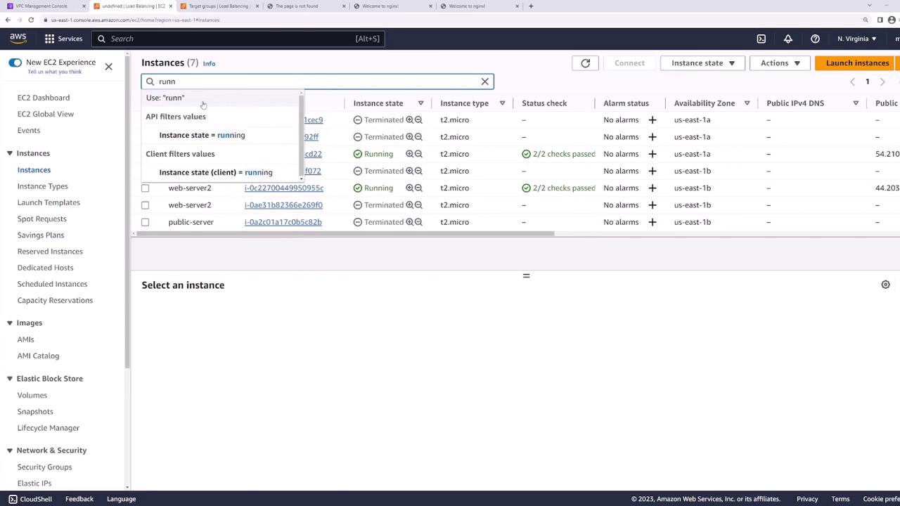
EC2 Instances
Our EC2 console shows both instances running:
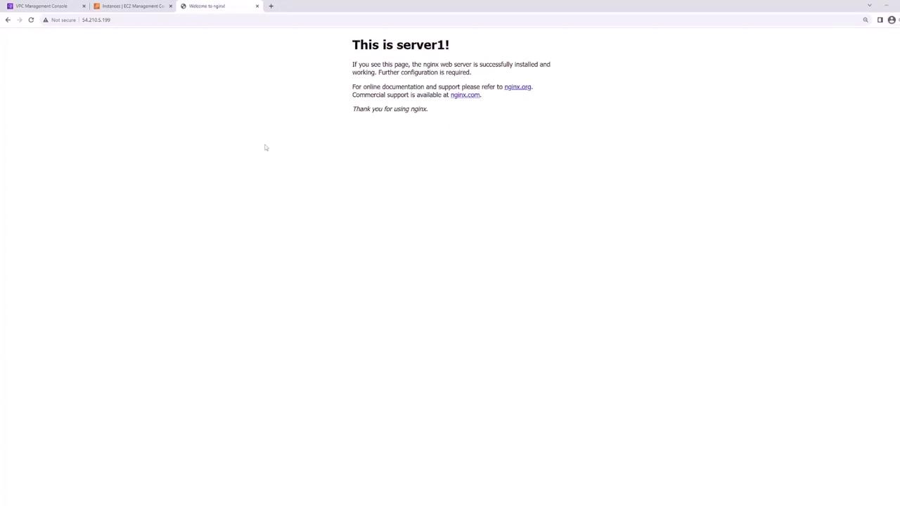
Visiting web-server-1 confirms Nginx is up:
And web-server-2 is similarly healthy:
Network Layout
Your VPC’s public subnets:
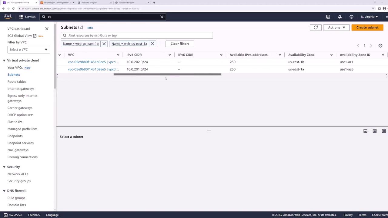
- web-us-east-1a: 10.0.201.0/24
- web-us-east-1b: 10.0.202.0/24
These subnets host your web servers and route traffic through the Internet Gateway.
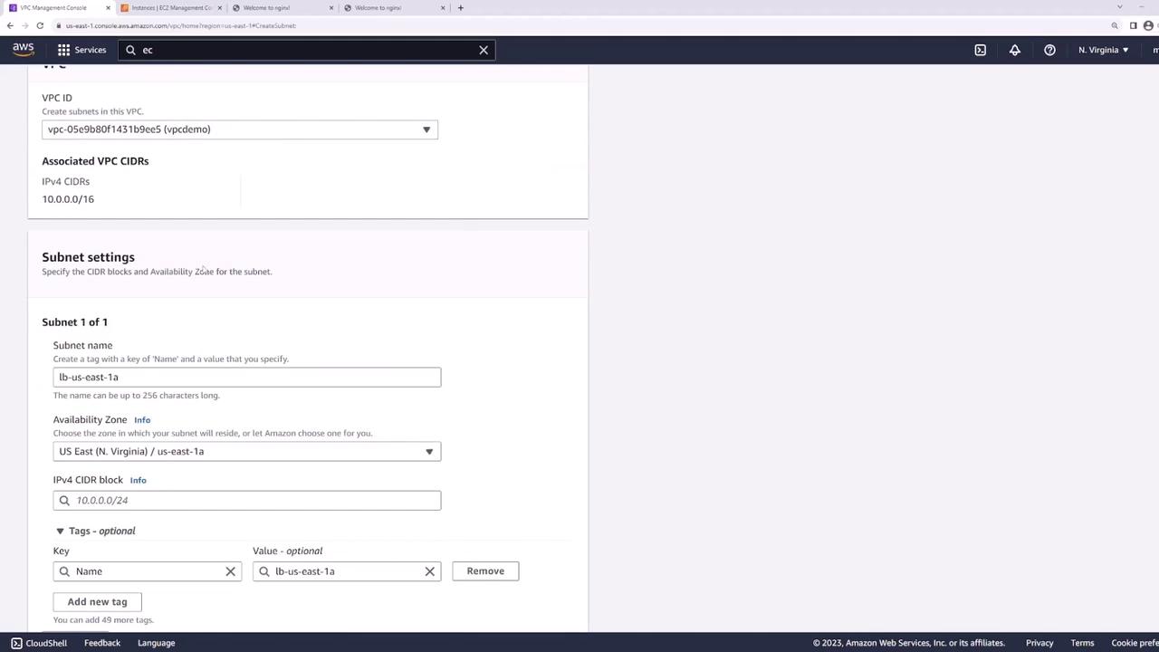
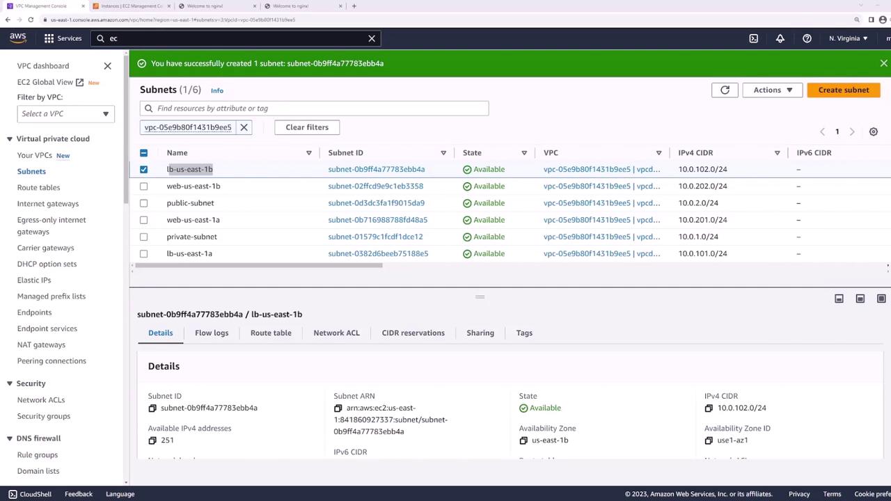
Step 1: Create Dedicated Subnets for the Load Balancer
Add two new public subnets—one in each AZ—for the ALB:
- In the VPC console, click Create Subnet.
- Configure:
- LB-us-east-1a: us-east-1a, 10.0.101.0/24
- LB-us-east-1b: us-east-1b, 10.0.102.0/24
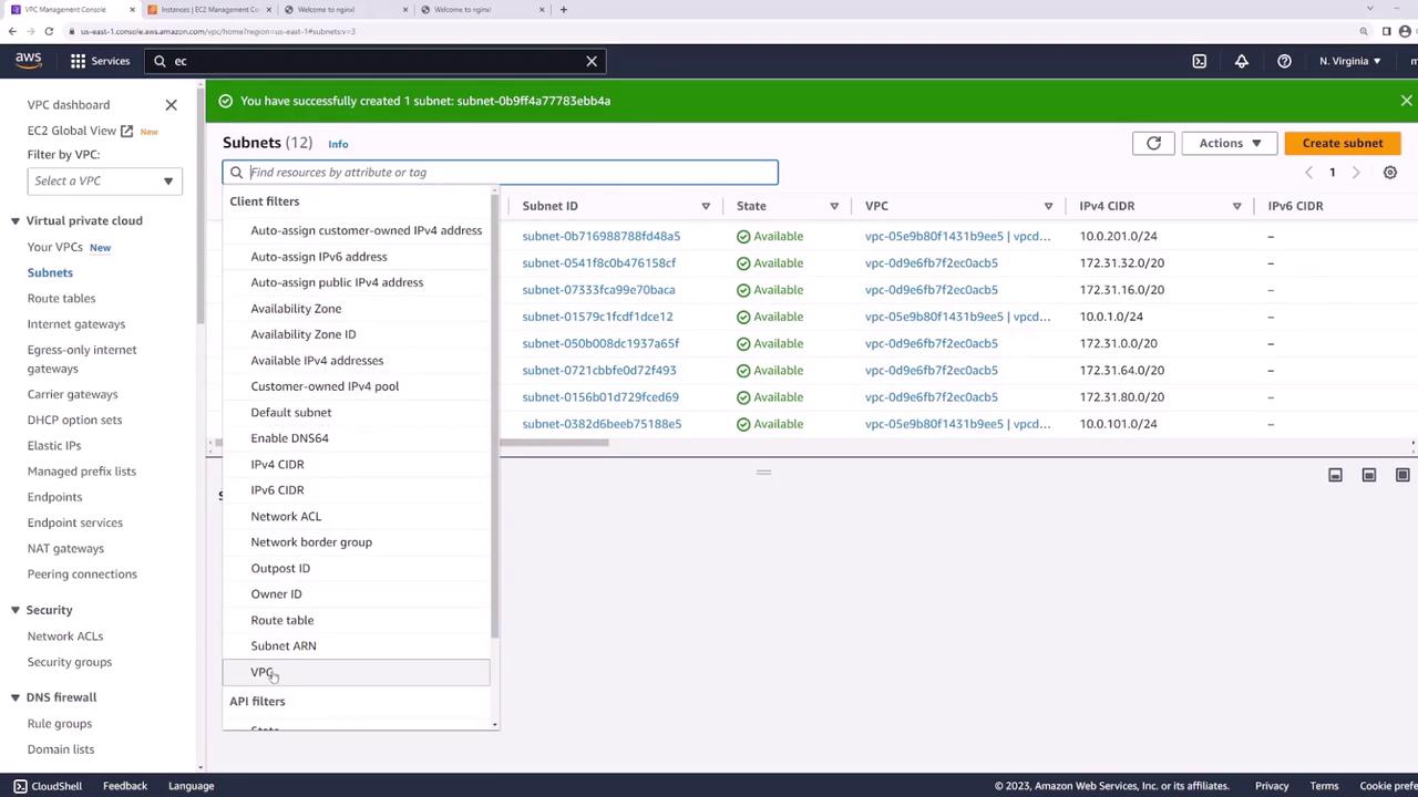
After creation, verify you have four public subnets:
Step 2: Verify Public Subnet Configuration
0.0.0.0/0) to the Internet Gateway—this makes the ALB internet-facing.
Select LB-us-east-1a (and LB-us-east-1b) to inspect its Route Table:
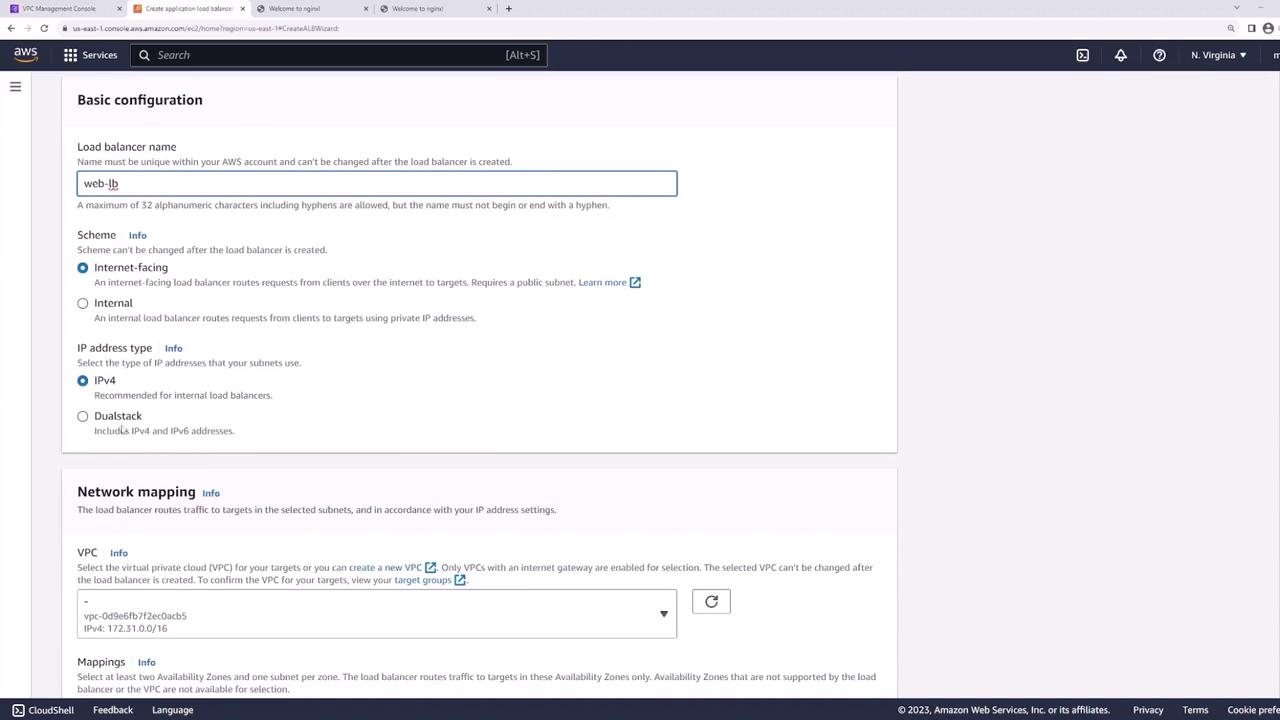
Step 3: Create the Application Load Balancer
- In the EC2 console, go to Load Balancers → Create Load Balancer → Application Load Balancer.
- Set:
- Name: web-lb
- Scheme: Internet-facing
- IP address type: IPv4
- VPC: demo
- Select subnets LB-us-east-1a and LB-us-east-1b.
Configure the ALB network mapping:
Attach a security group allowing HTTP (80) and HTTPS (443):

Step 4: Configure Listener and Target Group
Listener
Add an HTTP listener on port 80:
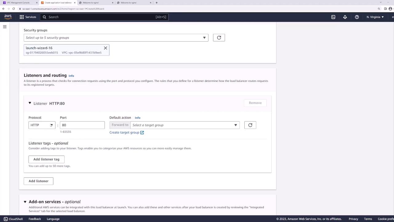
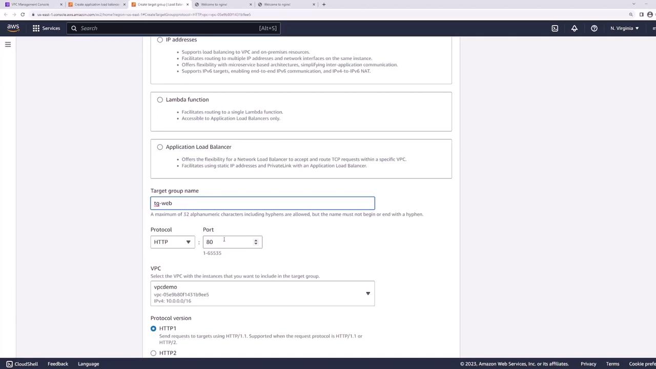
Target Group
- Create a new target group:
- Target type: Instances
- Name: web-targets
- Protocol: HTTP
- Port: 80
- VPC: demo
- Health check path:
/
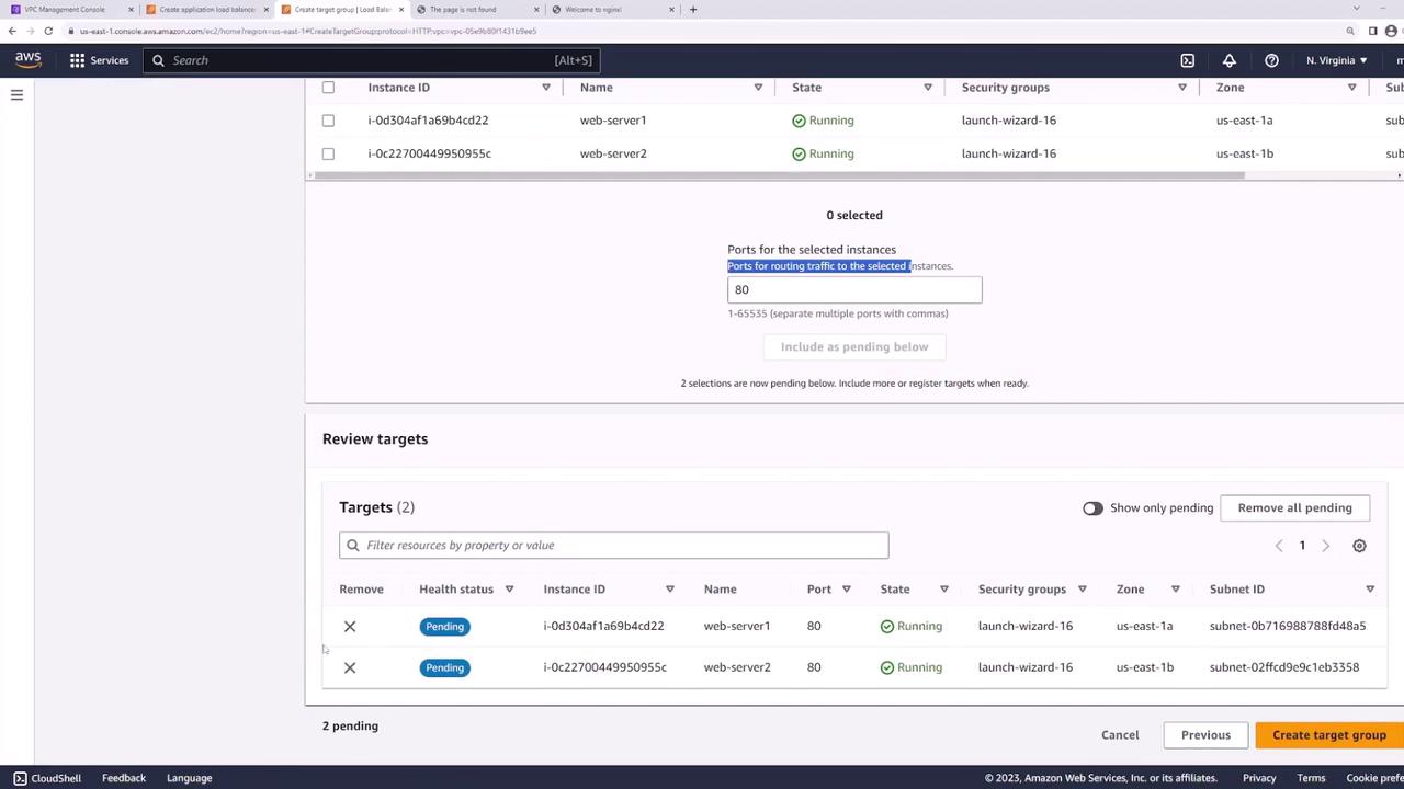
- Register web-server-1 and web-server-2 on port 80:
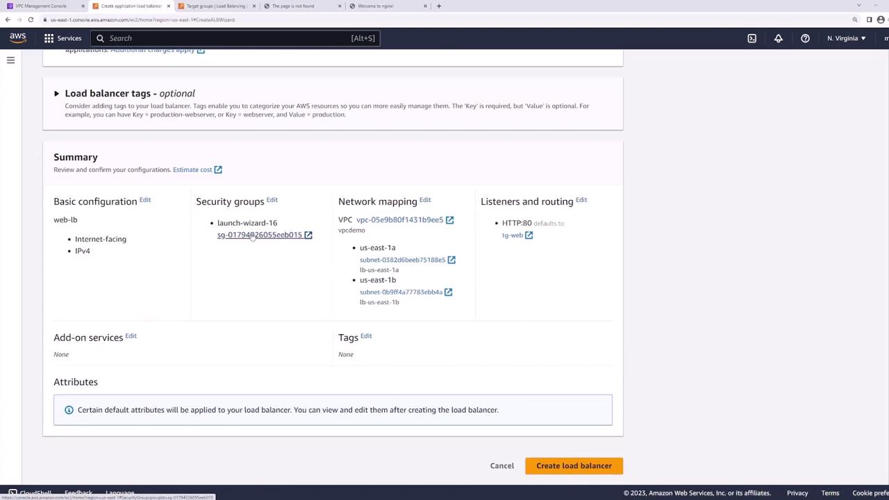
- Back in the ALB wizard, set web-targets as the default action for the HTTP listener:

- Review and create the ALB:
Step 5: Test the Load Balancer
Wait until the ALB status is active, then copy its DNS name:

From your terminal or browser:
bash  theme={null}
curl http://<load-balancer-dns-name>
Refreshing the request should alternate responses between server1 and server2, confirming traffic distribution.
Best Practice: Secure Your Web Servers
To harden your architecture:
- Move web servers into private subnets.
- Keep the ALB in public subnets.
- Configure the web servers’ security group to accept traffic only from the ALB’s security group.
This ensures all external requests pass through the ALB, improving security and isolation.